INDUSTRIAL VALVES & FLOW CONTROL TECHNICAL DATA
MODEL SG-041-6
Gear-Operated Wafer-Type Centerline Butterfly Valve
Product enquiry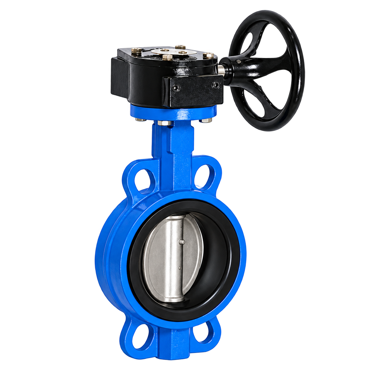
CONSTRUCTION
Materials / Main Components
| No. | Part Name | Material |
|---|---|---|
| 1 | Body | Ductile iron/CS/SS |
| 2 | Disc | Ductile iron/CS/SS |
| 3 | Pin | SS410/SS304/SS316 |
| 4 | Seat | EPDM/NBR |
| 5 | Stem | SS410/SS304/SS316 |
| 6 | Bushing | PTFE |
| 7 | O ring | NBR/EPDM/VITON |
| 8 | Worm gear | QT450-10/CS |
| 9 | Handwheel | QT450-10 |
| 10 | Bolt | Carbon Steel/SS304/SS316 |
RATING & STANDARDS
Main Technical Parameters
- Nominal pressure
- PN10/PN16, 125LB/150LB, 5K/10K/16KCatalogue-listed classes; pressure, size and material combinations require confirmation. Refer separately to the maximum-pressure conditions.
- Face to face standard
- GB/T12221, API609, EN558-1
- Test standard
- GB/T13927-2008, API598
- Applicable media
- Water, oil, gas, etc
APPLICATION & CONFIGURATION
Additional Information
Opening and flow information
The opening-angle/flow-coefficient illustration is qualitative only. Its percentage scale is not sufficiently defined to reproduce reliable numerical sizing coefficients. Obtain approved flow data before sizing.
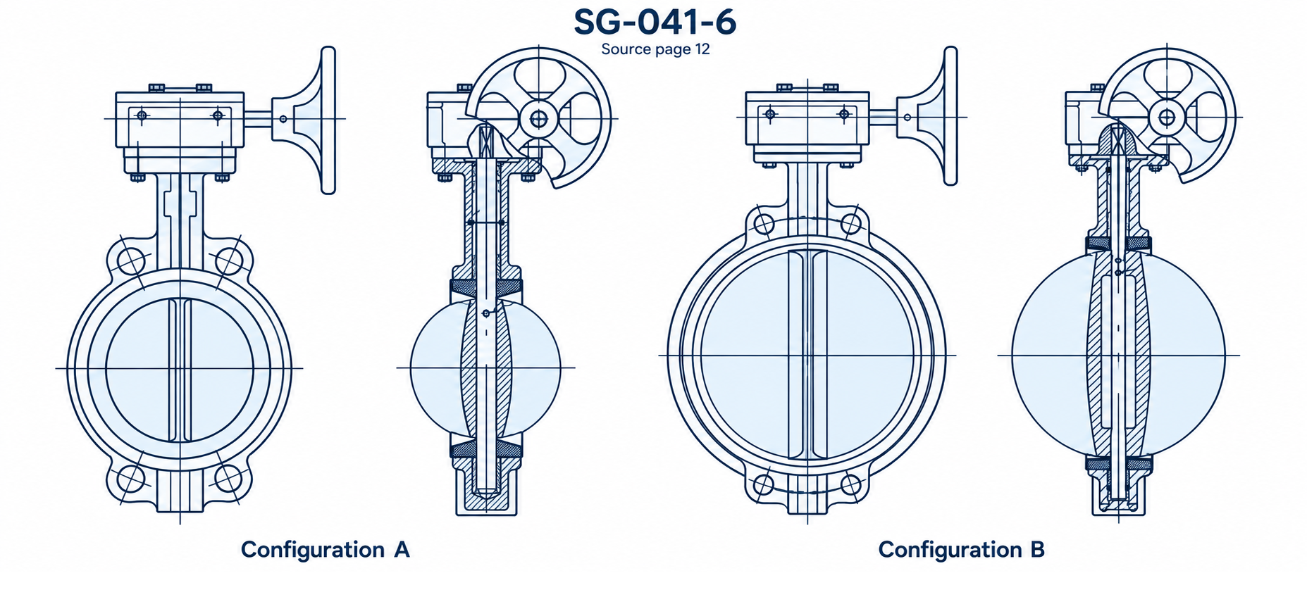
Illustrated configurations
Configuration A depicts DN40-DN300 and Configuration B depicts DN350-DN600. The illustrations do not establish the configuration of larger tabulated sizes.
SECTIONAL ILLUSTRATIONS
Sectional Illustrations
OPERATING LIMITS
Pressure Conditions
Listed operating and test pressures depend on the selected configuration. Confirm the applicable values and service conditions against the approved product submittal before selection.
| Size | Max Pressure (bar) | Min/Max Temperature (C) | Test Pressure (bar) / Shell | Test Pressure (bar) / Seat |
|---|---|---|---|---|
| DN40-DN600 | 10.0/16.0 | -10°C+100°C | 15.0/24.0 | 11.0/17.6 |
DIMENSIONAL DATA
Dimensions
Scroll horizontally to view all dimensions.
Units: mm
Inconsistent inch annotations and unconfirmed ANSI hole-count data are omitted. DN values and other checked dimensions are retained. Pressure applicability above DN600 is not confirmed.
| DN(mm) | A | B | C | D | PN10/16 / Phi D1 | PN10/16 / N-Phi d | ANSI150Lb / Phi D1 |
|---|---|---|---|---|---|---|---|
| 40 | 120 | 70 | 34 | 41.8 | 125 | 4-19 | 98.5 |
| 50 | 140 | 80 | 42 | 52.9 | 125 | 4-19 | 120.6 |
| 65 | 150 | 89 | 44.7 | 64.5 | 145 | 4-19 | 139.7 |
| 80 | 158 | 95 | 45.2 | 78.8 | 160 | 8-19 | 152.4 |
| 100 | 176 | 114 | 52 | 104 | 180 | 8-19 | 190.5 |
| 125 | 190 | 127 | 54.4 | 123.3 | 210 | 8-19 | 215.9 |
| 150 | 211 | 139 | 55.8 | 155.1 | 240 | 8-22 | 241.3 |
| 200 | 235 | 175 | 60.6 | 202.5 | 295 | 8-22/12-22 | 298.4 |
| 250 | 265 | 203 | 65.6 | 250.5 | 350/355 | 12-22/12-26 | 361.9 |
| 300 | 305 | 242 | 76.9 | 301.5 | 400/410 | 12-23/12-27 | 431.8 |
| 350 | 368 | 267 | 76.5 | 333.3 | 460/470 | 16-23/16-31 | 476.2 |
| 400 | 405 | 321 | 102 | 389.6 | 515/525 | 16-28/16-31 | 539.5 |
| 450 | 422 | 328 | 114 | 440.5 | 565/585 | 20-28/20-31 | 577.8 |
| 500 | 480 | 361 | 127 | 491.6 | 620/650 | 20-28/20-34 | 635 |
| 550 | 692.2 | ||||||
| 600 | 562 | 459 | 152 | 592.5 | 725/770 | 20-31/20-37 | 749.5 |
| 700 | 624 | 520 | 165 | 695 | 840 | 24-31/24-37 | 863.6 |
| 750 | 914.4 | ||||||
| 800 | 672 | 591 | 190 | 794.7 | 950 | 24-34/24-41 | 977.9 |
| 900 | 720 | 656 | 203 | 864.7 | 1050 | 28-34/28-41 | 1085.8 |
| 1000 | 800 | 721 | 216 | 965 | 1160/1170 | 28-37/28-44 | 1200.2 |
| 1200 | 941 | 864 | 254 | 1160.6 | 1380/1390 | 32-41/32-50 | 1422.4 |
Verify the selected configuration and service duty against the approved product submittal.