INDUSTRIAL VALVES & FLOW CONTROL TECHNICAL DATA
MODEL SG-064-1
Straight-Type Globe Valve
Product enquiry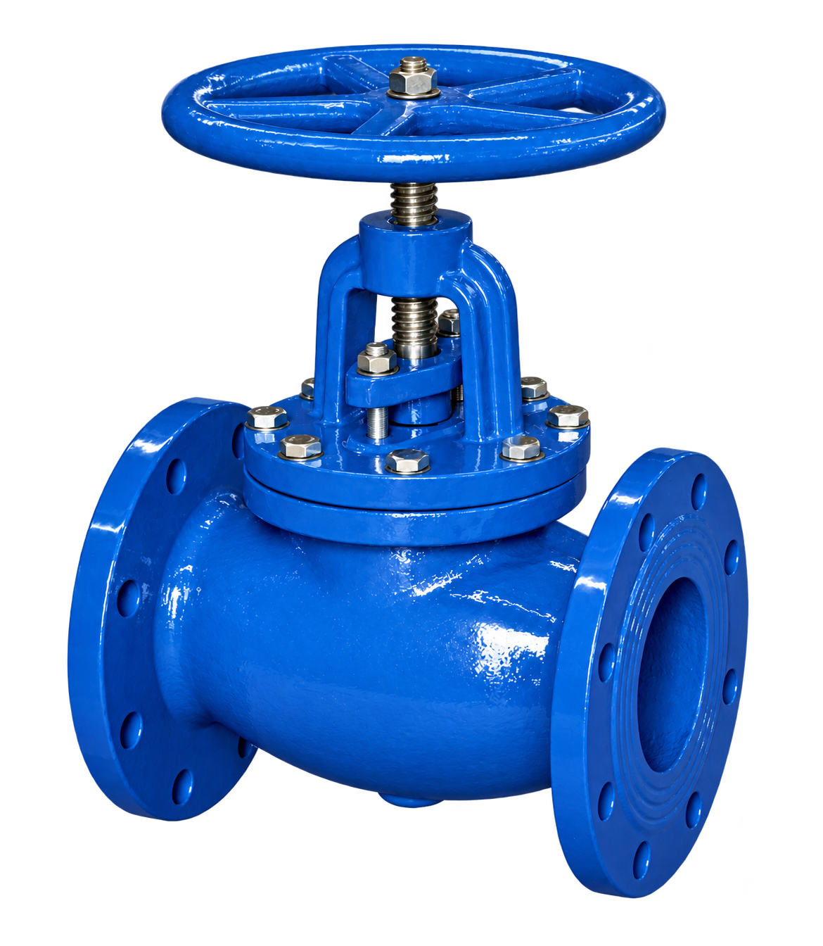
01
CONSTRUCTION
Materials / Main Components
| No. | Part Name | Material |
|---|---|---|
| 1 | Body | Ductile iron/CS/SS |
| 2 | Sealing face | SS304/SS316 |
| 3 | Disc | 20Cr13/SS304/SS316 |
| 4 | Steel Ball | SS304/SS316 |
| 5 | Stem | SS410/SS304/SS316/Brass HPb59-1 |
| 6 | Gasket | Graphite/EPDM/NBR |
| 7 | Packing | Graphite |
| 8 | Packing Gland | Ductile iron/CS/SS |
| 9 | Bonnet | Ductile iron/CS/SS |
| 10 | Nut | Brass HPb59-1 |
| 11 | Handwheel | Ductile iron |
| 12 | Hexagonal Nut | SS304/316 |
| 13 | Bolt | Carbon Steel/SS304/SS316 |
| 14 | Nut | Carbon Steel/SS304/SS316 |
02
RATING & STANDARDS
Main Technical Parameters
- Nominal pressure
- PN10/PN16/PN25/PN40/PN64, 125LB/150LB/300LB, 5K/10K/16K
- Face to face standard
- GB/T12221-2005, ASME B16.10, DIN F6, JIS B2002Standards applicability requires confirmation for the selected configuration; a conflicting source designation is omitted.
- Flange connection standard
- GB/T17241.6, GB/T9113-2010, EN1092-2, JIS B2212
- Test standard
- GB/T13927-2008, API598
- Applicable media
- Water, oil, gas, etc
03
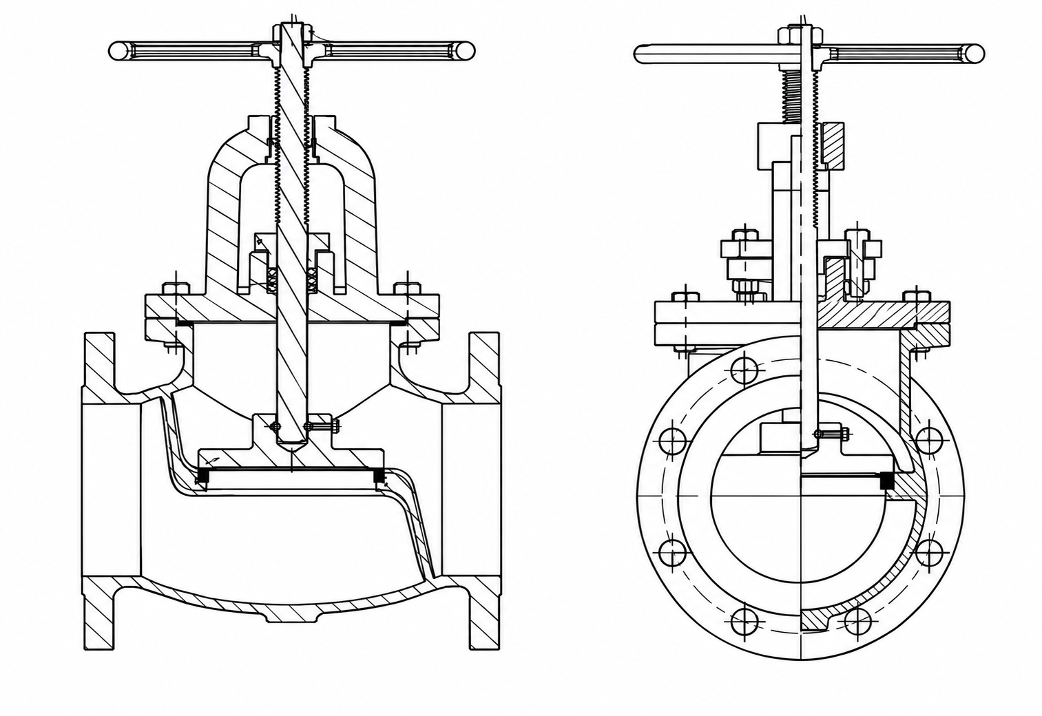
SECTIONAL ILLUSTRATIONS
Sectional Illustrations
04
OPERATING LIMITS
Pressure Conditions
Listed operating and test pressures depend on the selected configuration. Confirm the applicable values and service conditions against the approved product submittal before selection.
| Size | Max Pressure (bar) | Min/Max Temp (°C) | Test Pressure (bar) / Shell | Test Pressure (bar) / Seat |
|---|---|---|---|---|
| DN40-DN300 | 10.0/16.0/25.0 | -10°C+220°C | 15.0/24.0/37.5 | 11.0/17.6/27.5 |
05
DIMENSIONAL DATA
Dimensions
Scroll horizontally to view all dimensions.
The stated pressure-condition range is DN40-DN300; smaller dimensional rows do not extend that range.
| DN(mm) & INCH | GB/T12221 BS5152 | ANSI B16.10 | JIS B2002 | EN1092-2 / PN10/16 / D | EN1092-2 / PN10/16 / K | EN1092-2 / PN10/16 / n-Φd | EN1092-2 / PN25 / D | EN1092-2 / PN25 / K | EN1092-2 / PN25 / n-Φd | ANSI B16.1 / CL125/150 / D | ANSI B16.1 / CL125/150 / K | ANSI B16.1 / CL125/150 / n-Φd | H |
|---|---|---|---|---|---|---|---|---|---|---|---|---|---|
| 15(½") | 108 | 108 | 108 | 95 | 65 | 4-14 | 95 | 65 | 4-14 | 89 | 60.5 | 4-15 | 200 |
| 20(¾") | 117 | 117 | 117 | 105 | 75 | 4-14 | 105 | 75 | 4-14 | 98 | 70 | 4-15 | 204 |
| 25(1") | 127 | 127 | 127 | 115 | 85 | 4-14 | 115 | 85 | 4-14 | 108 | 79.5 | 4-15 | 209 |
| 32(1¼") | 140 | 140 | 140 | 140 | 100 | 4-19 | 140 | 100 | 4-19 | 117 | 89 | 4-15 | 218 |
| 40(1½") | 165 | 165 | 165 | 150 | 110 | 4-19 | 150 | 110 | 4-19 | 127 | 98.5 | 4-15 | 250 |
| 50(2") | 203 | 203 | 203 | 165 | 125 | 4-19 | 165 | 125 | 4-19 | 152 | 120.5 | 4-19 | 266 |
| 65(2½") | 216 | 216 | 216 | 185 | 145 | 4-19 | 185 | 145 | 4-19 | 178 | 139.5 | 4-19 | 279 |
| 80(3") | 241 | 241 | 241 | 200 | 160 | 8-19 | 200 | 160 | 8-19 | 190 | 152.5 | 4-19 | 304 |
| 100(4") | 292 | 292 | 292 | 220 | 180 | 8-19 | 235 | 190 | 8-23 | 229 | 190.5 | 8-19 | 405 |
| 125(5") | 330 | 330 | 330 | 250 | 210 | 8-19 | 270 | 220 | 8-28 | 254 | 216 | 8-22 | 450 |
| 150(6") | 356 | 356 | 356 | 285 | 240 | 8-23 | 300 | 250 | 8-28 | 279 | 241.5 | 8-22 | 550 |
| 200(8") | 495 | 495 | 495 | 340 | 295 | 8-23/12-23 | 360 | 310 | 12-28 | 343 | 298.5 | 12-22 | 710 |
| 250(10") | 622 | 622 | 622 | 395/405 | 350/355 | 12-23/12-27 | 425 | 370 | 12-31 | 406 | 362 | 12-25 | 880 |
| 300(12") | 698 | 698 | 698 | 445/460 | 400/410 | 12-23/12-27 | 485 | 430 | 16-31 | 483 | 432 | 12-25 | 1000 |
Verify the selected configuration and service duty against the approved product submittal.