Construction & selection
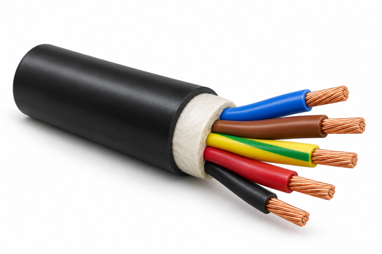
Five-core copper cables with XLPE insulation. The illustration shows an unarmoured configuration with a common PVC sheath; armour and alternative sheath compounds require separate selection.
For technical data and a quotation, use Contact in the main navigation and include this cable family in your enquiry.
Construction
Illustrated variant: CU/XLPE/PVC unarmoured
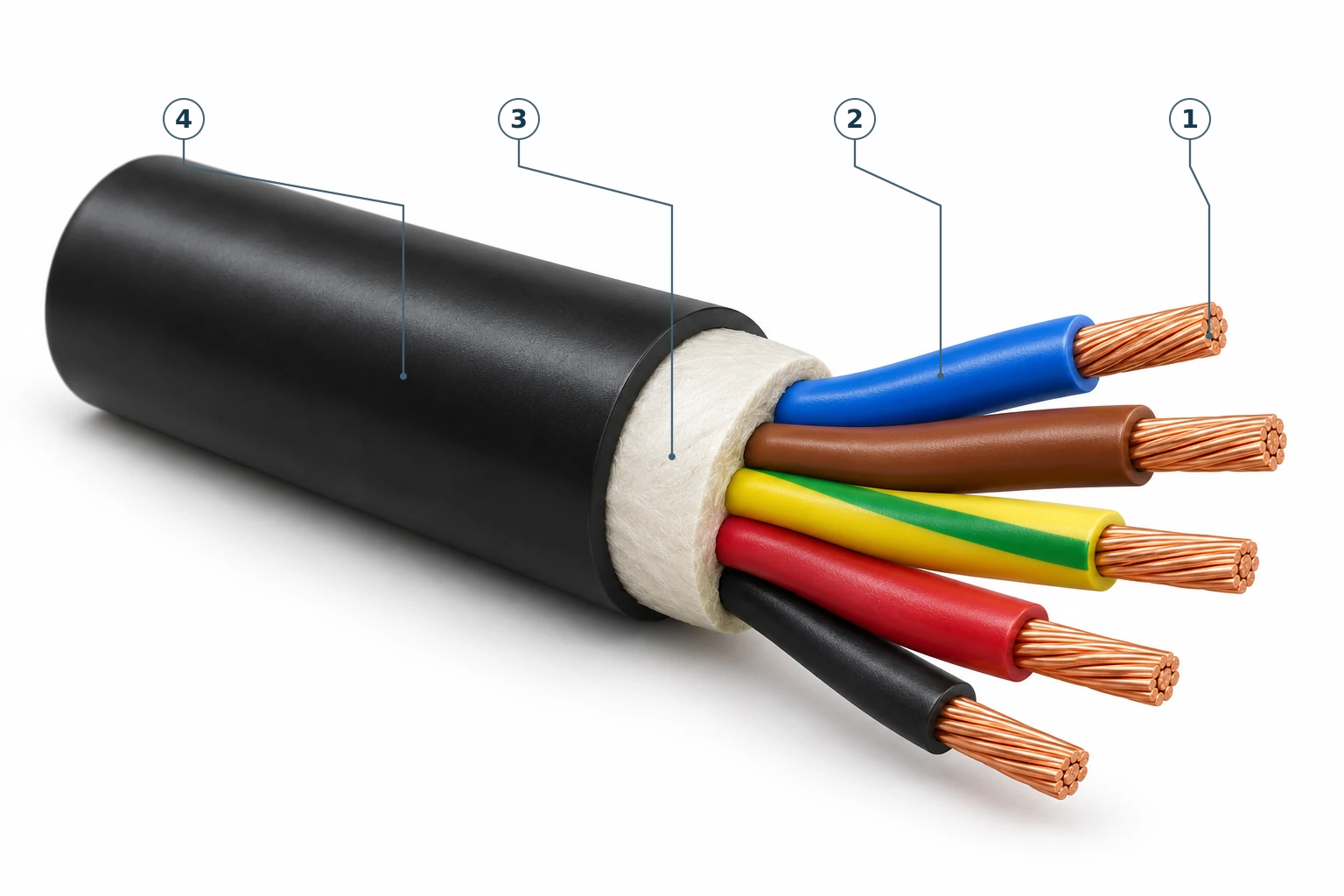
- Copper conductors
The copper conductors form the current-carrying elements of the insulated cores.
- XLPE insulation
Cross-linked polyethylene forms the main electrical insulation around each conductor.
- Core assembly and fillers
The insulated cores are assembled together, with fillers occupying the spaces between them.
- PVC outer sheath
PVC forms the external protective covering around the cable assembly.
Construction source: supplier LV reference catalogue, page 45.
Family reference
| Illustrated conductor | Copper |
|---|---|
| Illustrated configuration | CU/XLPE/PVC unarmoured |
| Construction layers | five stranded copper cores; individual XLPE insulation; filler; PVC outer sheath |
| Reference voltage family | 600/1000 V catalogue family; confirm the selected current datasheet |
| Selection requirement | Confirm size, rated voltage, installation conditions and applicable standards before ordering |
Technical specifications
Five-core copper XLPE — unarmoured
- Rated voltage
- 600/1000 V
- Construction
- CU/XLPE/PVC(PE); sheath alternatives as source
- Standards — catalogue-stated
- IEC 60502-1 across the listed sizes; generally BS 5467 for 16–400 mm² as stated in the supplier catalogue.
Reference catalogue data for the selected construction, not certification or a guarantee of current availability. Confirm the current datasheet before ordering.
| Nominal conductor area (mm²) | Maximum conductor resistance at 20°C (Ω/km) | Insulation thickness (mm) | Outer sheath thickness (mm) | Approximate overall diameter (mm) | Approximate cable weight (kg/km) |
|---|---|---|---|---|---|
| 1.5* | 12.1 | 0.7 | 1.8 | 12.3 | 189 |
| 1.5 | 12.1 | 0.7 | 1.8 | 12.9 | 198 |
| 2.5* | 7.41 | 0.7 | 1.8 | 13.4 | 247 |
| 2.5 | 7.41 | 0.7 | 1.8 | 14.0 | 256 |
| 4 | 4.61 | 0.7 | 1.8 | 15.5 | 346 |
| 6 | 3.08 | 0.7 | 1.8 | 17.0 | 458 |
| 10 | 1.83 | 0.7 | 1.8 | 19.4 | 665 |
| 16 | 1.15 | 0.7 | 1.8 | 22.2 | 973 |
| 25 | 0.727 | 0.9 | 1.8 | 25.9 | 1469 |
| 35 | 0.524 | 0.9 | 1.8 | 28.6 | 1946 |
| 50 | 0.387 | 1.0 | 1.9 | 29.9 | 2491 |
| 70 | 0.268 | 1.1 | 2.1 | 34.8 | 3544 |
| 95 | 0.193 | 1.1 | 2.2 | 39.1 | 4794 |
| 120 | 0.153 | 1.2 | 2.4 | 43.5 | 6004 |
| 150 | 0.124 | 1.4 | 2.6 | 48.4 | 7423 |
| 185 | 0.0991 | 1.6 | 2.8 | 53.9 | 9293 |
| 240 | 0.0754 | 1.7 | 3.0 | 54.8 | 9730 |
| 300 | 0.0601 | 1.8 | 3.2 | 66.8 | 14982 |
| 400 | 0.0470 | 2.0 | 3.5 | 74.9 | 19224 |
| 500 | 0.0366 | 2.2 | 3.8 | 84.1 | 24610 |
- * denotes circular solid Class 1. Other conductors through 16 mm² are circular stranded Class 2; 25 mm² and larger are shaped stranded Class 2.
- PVC and PE sheath alternatives require confirmation; table values are not a statement of equivalent compound performance.
Source: supplier LV reference catalogue, PDF page 45 (printed 42). Approximate values are identified in column headings. Asterisks retain source conductor variants.
Project-specific confirmation
Confirm the required conductor material, core arrangement, voltage designation, installation conditions, size and applicable standards with your enquiry. Reference tables on this page give data for the stated construction; confirm the selected current datasheet before ordering.
Illustrations are not engineering drawings or factory photographs. Final specifications and approved drawings will be confirmed with our official quotation. No certification or current manufacturer availability is implied by this family overview.