INDUSTRIAL VALVES & FLOW CONTROL TECHNICAL DATA
MODEL SG-041-7
Gear-Operated Flanged Centerline Butterfly Valve
Product enquiry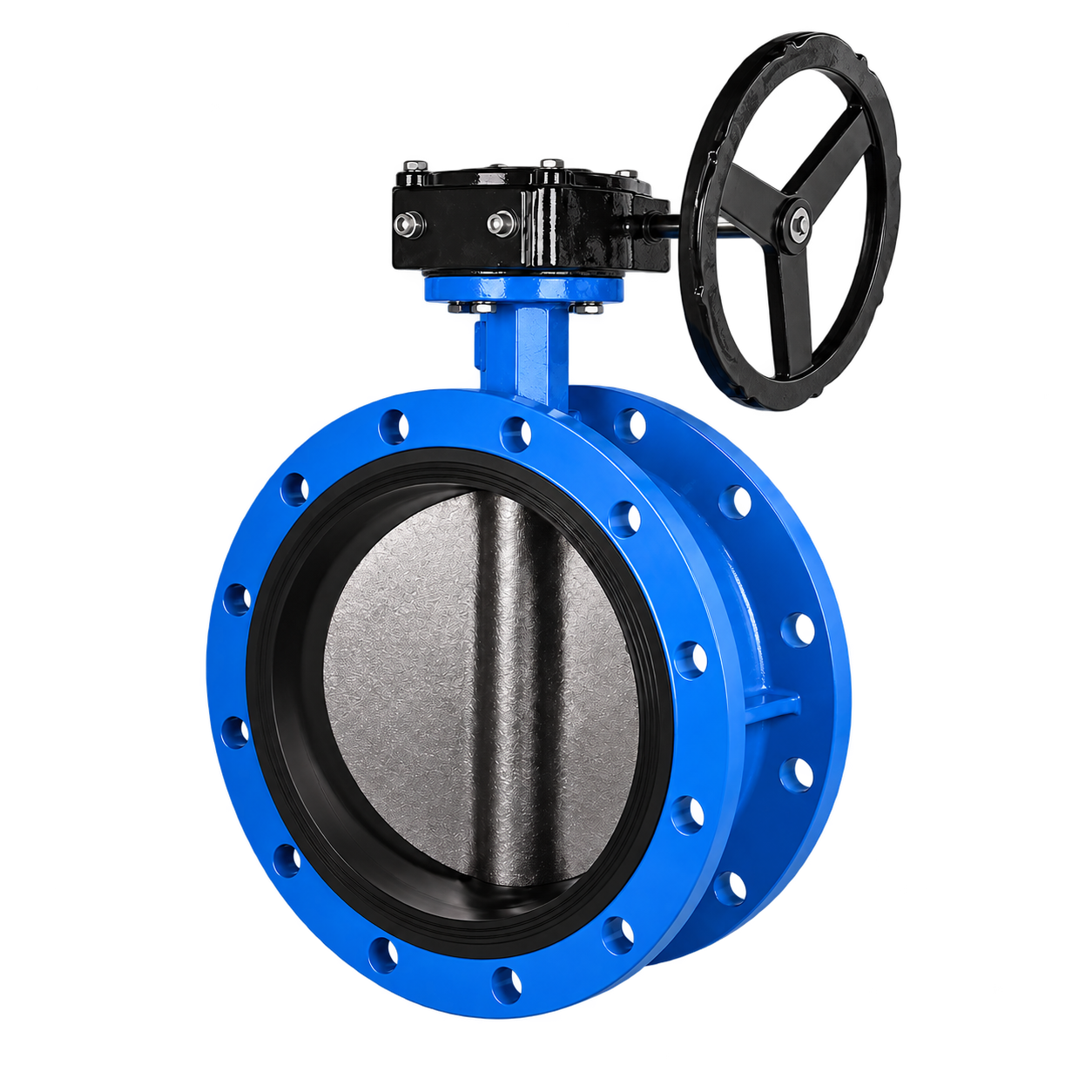
CONSTRUCTION
Materials / Main Components
| No. | Part Name | Material |
|---|---|---|
| 1 | Body | Ductile iron/CS/SS |
| 2 | Stem | SS410/SS304/SS316 |
| 3 | Seal ring | QT450-10/CF8/CF8M |
| 4 | Disc | Ductile iron/CS/SS |
| 5 | Platen | Ductile iron |
| 6 | Packing gland | Ductile iron |
| 7 | O ring | EPDM/NBR |
| 8 | Worm gear | Ductile iron/CS |
RATING & STANDARDS
Main Technical Parameters
- Nominal pressure
- PN10/PN16/PN25/PN40/PN64, 125LB/150LB, 5K/10K/16KCatalogue-listed classes; pressure, size and material combinations require confirmation. Refer separately to the maximum-pressure conditions.
- Face to face standard
- GB/T12221, API609, EN558-1
- Flange connection standard
- GB/T17241.6, GB/T9113-2010, EN1092-2
- Test standard
- GB/T13927-2008, API598
- Applicable media
- Water, oil, gas, etc
APPLICATION & CONFIGURATION
Additional Information
Opening and flow information
The opening-angle/flow-coefficient illustration is qualitative only. Its percentage scale is not sufficiently defined to reproduce reliable numerical sizing coefficients. Obtain approved flow data before sizing.
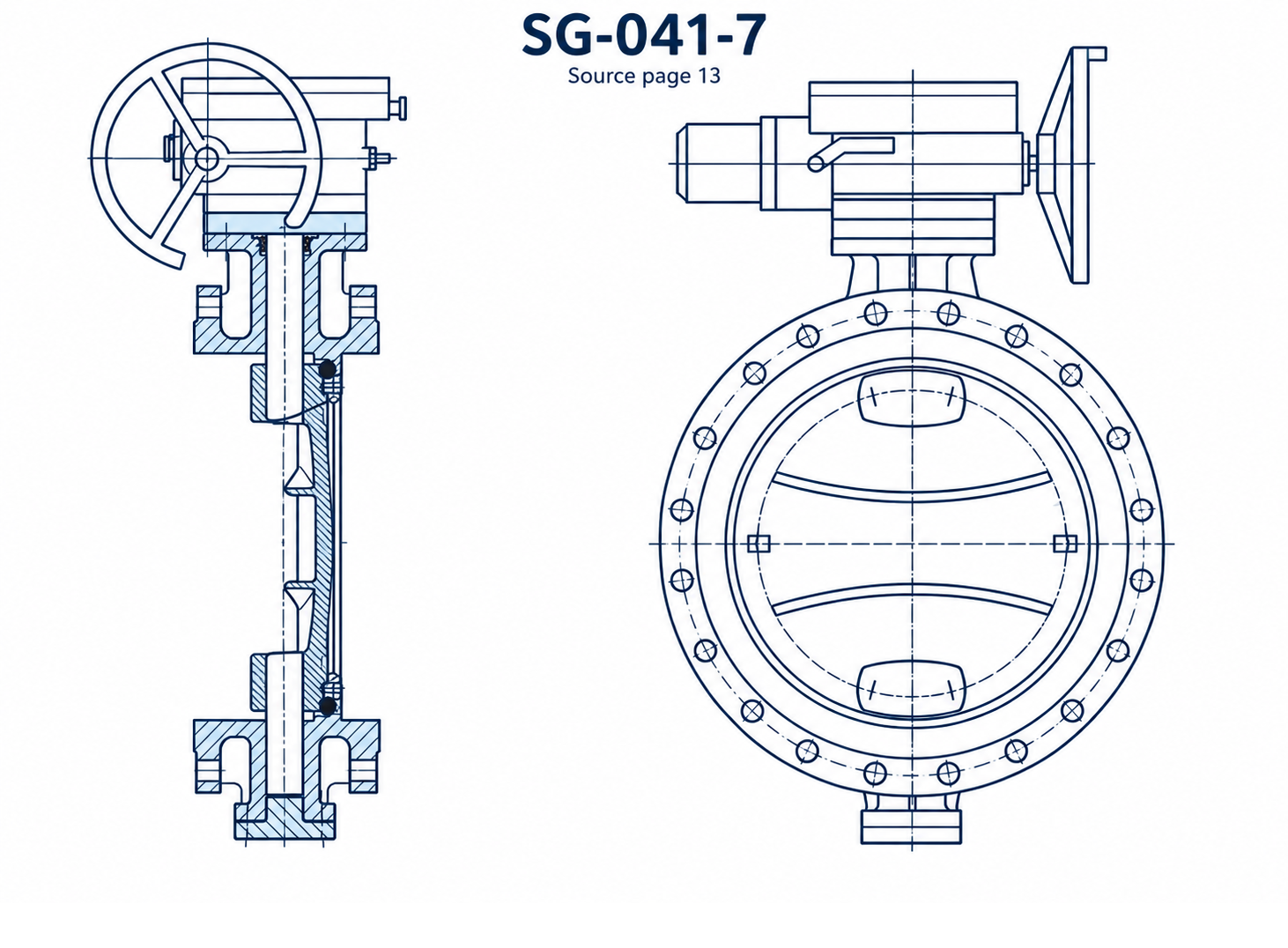
SECTIONAL ILLUSTRATIONS
Sectional Illustrations
OPERATING LIMITS
Pressure Conditions
Listed operating and test pressures depend on the selected configuration. Confirm the applicable values and service conditions against the approved product submittal before selection.
| Size | Max Pressure (bar) | Min/Max Temperature (C) | Test Pressure (bar) / Shell | Test Pressure (bar) / Seat |
|---|---|---|---|---|
| DN40-DN600 | 10.0/16.0 | -10°C+100°C | 15.0/24.0 | 11.0/17.6 |
DIMENSIONAL DATA
Dimensions
Scroll horizontally to view all dimensions.
Units: mm
Two unconfirmed H1 values are marked for confirmation because the source values are inconsistent with the surrounding series. No corrected dimensions are inferred.
| DN(mm) & INCH | L | H1 | H2 | EN1092-2 / PN10/16 / D | EN1092-2 / PN10/16 / K | EN1092-2 / PN10/16 / n-Phi d | EN1092-2 / PN25 / D | EN1092-2 / PN25 / K | EN1092-2 / PN25 / n-Phi d |
|---|---|---|---|---|---|---|---|---|---|
| 50(2") | 108 | 127 | 82 | 165 | 125 | 4-19 | 165 | 125 | 4-19 |
| 65(2½") | 112 | Not specified — confirm | 95 | 185 | 145 | 4-19 | 185 | 145 | 4-19 |
| 80(3") | 114 | 143 | 98 | 200 | 160 | 8-19 | 200 | 160 | 8-19 |
| 100(4") | 127 | Not specified — confirm | 110 | 220 | 180 | 8-19 | 235 | 190 | 8-23 |
| 125(5") | 140 | 170 | 125 | 250 | 210 | 8-19 | 270 | 220 | 8-28 |
| 150(6") | 140 | 188 | 143 | 285 | 240 | 8-23 | 300 | 250 | 8-28 |
| 200(8") | 152 | 225 | 170 | 340 | 295 | 8-23/12-23 | 360 | 310 | 12-28 |
| 250(10") | 165 | 267 | 205 | 395/405 | 350/355 | 12-23/12-27 | 425 | 370 | 12-31 |
| 300(12") | 178 | 303 | 233 | 445/460 | 400/410 | 12-23/12-27 | 485 | 430 | 16-31 |
| 350(14") | 190 | 325 | 255 | 505/520 | 460/470 | 16-23/16-31 | 555 | 490 | 16-34 |
| 400(16") | 216 | 365 | 285 | 565/580 | 515/525 | 16-28/16-31 | 620 | 550 | 16-37 |
| 450(18") | 222 | 390 | 320 | 615/640 | 565/585 | 20-28/20-31 | 670 | 600 | 20-37 |
| 500(20") | 229 | 427 | 352 | 670/715 | 620/650 | 20-28/20-34 | 730 | 660 | 20-37 |
| 600(24") | 267 | 505 | 410 | 780/840 | 725/770 | 20-31/20-37 | 845 | 770 | 20-41 |
| 700(28") | 292 | 570 | 450 | 895/910 | 840 | 24-31/24-37 | |||
| 800(32") | 318 | 633 | 513 | 1015/1025 | 950 | 24-34/24-41 | |||
| 900(36") | 330 | 690 | 575 | 1115/1125 | 1050 | 28-34/28-41 | |||
| 1000(40") | 410 | 690 | 585 | 1230/1255 | 1160/1170 | 28-37/28-44 | |||
| 1200(48") | 470 | 930 | 800 | 1455/1485 | 1380/1390 | 32-41/32-50 |
Verify the selected configuration and service duty against the approved product submittal.