INDUSTRIAL VALVES & FLOW CONTROL TECHNICAL DATA
MODEL SG-071-2-2
Flange End Resilient Seat Gate Valve-NRS (Gland Cap)
Technical specifications and configuration information.
Product enquiry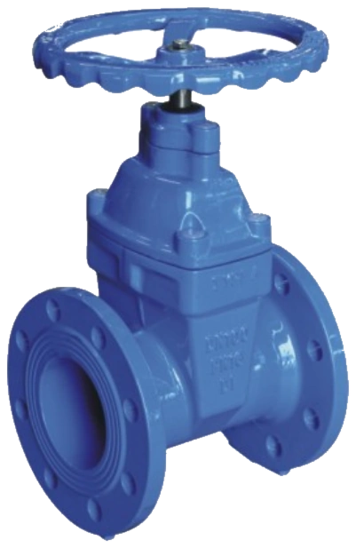
01
CONSTRUCTION
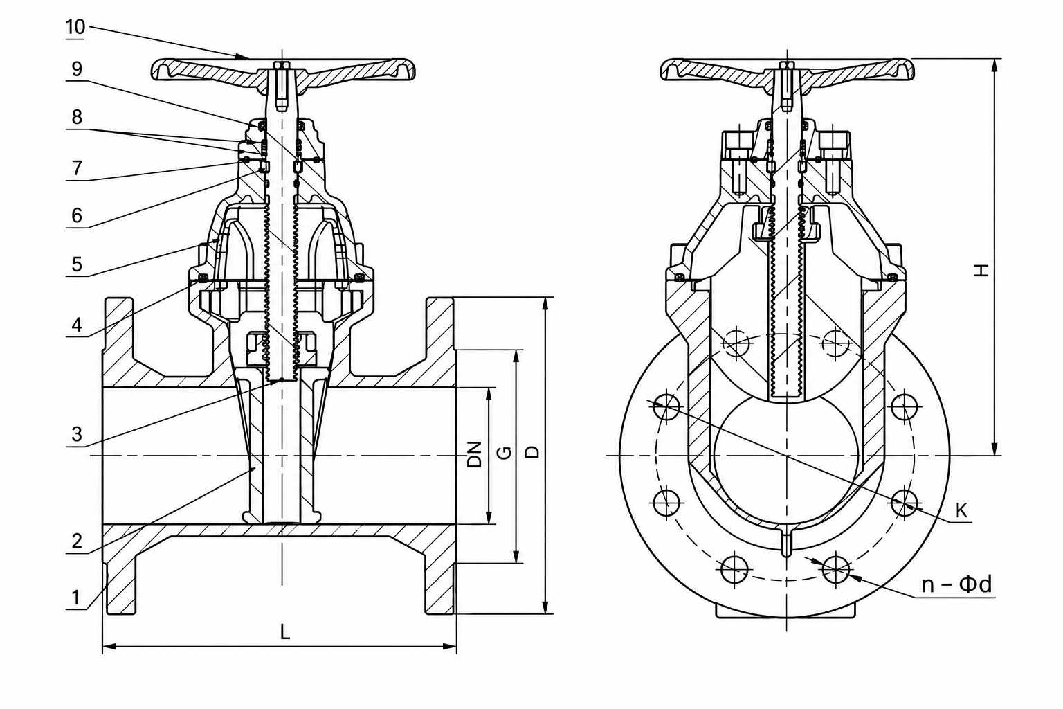
Materials / Main Components
| No. | Part Name | Material |
|---|---|---|
| 1 | Body | Ductile iron/CS/SS |
| 2 | Disc | Ductile iron/CS+EPDM |
| 3 | Stem | SS410/SS304/SS316/Brass HPb59-1 |
| 4 | Gasket | EPDM/NBR |
| 5 | Bonnet | Ductile iron/CS/SS |
| 6 | Locating ring | Brass HPb59-1 |
| 7 | Stem nut | Brass HPb59-1 |
| 8 | Pads | Graphite/EPDM/NBR |
| 9 | Dust ring | EPDM |
| 10 | Handwheel | Ductile iron |
02
RATING & STANDARDS
Main Technical Parameters
- Face-to-face standard
- GB/T 12221-2005; ANSI B16.10; DIN 3352 F4/F5; EN 558-1
- Flange connection standard
- GB/T 17241.6; GB/T 9113-2010; EN 1092-2; ANSI B16.1/B16.5
- Test standard
- GB/T 13927-2008; API 598
- Applicable media
- Water, oil, gas, etc.
- Available configurations
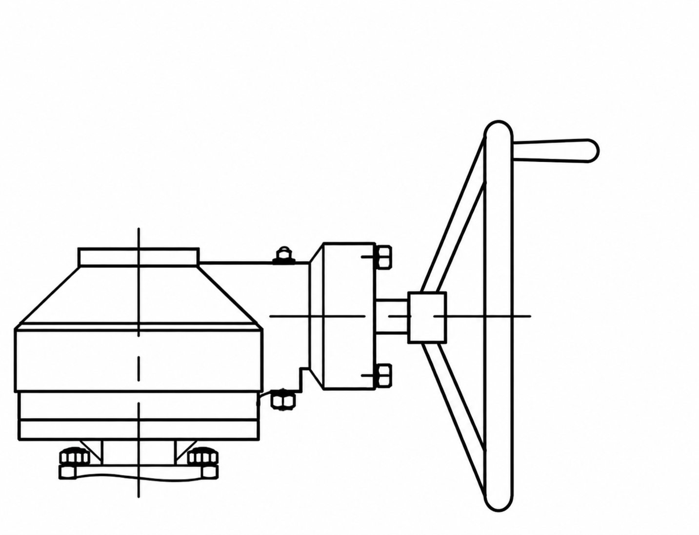
- Available with gear, electric operator, etc.
- Drawing note
- Optional square operating head for buried installation.
03
SECTIONAL ILLUSTRATIONS
Sectional Illustrations
Use the inspection control to enlarge the sectional illustrations.
04
OPERATING LIMITS
Maximum Pressure Conditions
Listed operating and test pressures depend on the selected configuration. Confirm the applicable values and service conditions against the approved product submittal before selection.
| Size | Max Pressure (bar) | Min/Max Temp (°C) | Shell Test Pressure (bar) | Seat Test Pressure (bar) |
|---|---|---|---|---|
| DN40–DN1600 | 10.0/16.0/25.0 | −10°C+100°C | 15.0/24.0/37.5 | 11.0/17.6/27.5 |
05
DIMENSIONAL DATA
Dimensions
Dimensions are listed by size and connection standard. Blank cells indicate that no value is provided; they do not indicate zero.
| DN (mm) / inch | GB/T 12221 BS 5163 | DIN 3352 F4/F5 | ANSI B16.10 | EN 1092-2 | ANSI B16.1 | H | |||||||
|---|---|---|---|---|---|---|---|---|---|---|---|---|---|
| PN10/16 | PN25 | CL125/150 | |||||||||||
| L | L | L | D | K | n-Φd | D | K | n-Φd | D | K | n-Φd | ||
| 40 (1½″) | 165 | 140/240 | 165 | 150 | 110 | 4-19 | 150 | 110 | 4-19 | 127 | 98.5 | 4-15 | 220 |
| 50 (2″) | 178 | 150/250 | 178 | 165 | 125 | 4-19 | 165 | 125 | 4-19 | 152 | 120.5 | 4-19 | 230 |
| 65 (2½″) | 190 | 170/270 | 190 | 185 | 145 | 4-19 | 185 | 145 | 4-19 | 178 | 139.5 | 4-19 | 260 |
| 80 (3″) | 203 | 180/280 | 203 | 200 | 160 | 8-19 | 200 | 160 | 8-19 | 190 | 152.5 | 4-19 | 290 |
| 100 (4″) | 229 | 190/300 | 229 | 220 | 180 | 8-19 | 235 | 190 | 8-23 | 229 | 190.5 | 8-19 | 315 |
| 125 (5″) | 254 | 200/325 | 254 | 250 | 210 | 8-19 | 270 | 220 | 8-28 | 254 | 216 | 8-22 | 365 |
| 150 (6″) | 267 | 210/350 | 267 | 285 | 240 | 8-23 | 300 | 250 | 8-28 | 279 | 241.5 | 8-22 | 400 |
| 200 (8″) | 292 | 230/400 | 292 | 340 | 295 | 8-23/12-23 | 360 | 310 | 12-28 | 343 | 298.5 | 12-22 | 495 |
| 250 (10″) | 330 | 250/450 | 330 | 395/405 | 350/355 | 12-23/12-27 | 425 | 370 | 12-31 | 406 | 362 | 12-25 | 630 |
| 300 (12″) | 356 | 270/500 | 356 | 445/460 | 400/410 | 12-23/12-27 | 485 | 430 | 16-31 | 483 | 432 | 12-25 | 680 |
| 350 (14″) | 381 | 290/550 | 381 | 505/520 | 460/470 | 16-23/16-31 | 555 | 490 | 16-34 | 533 | 476.5 | 12-29 | 790 |
| 400 (16″) | 406 | 310/600 | 406 | 565/580 | 515/525 | 16-28/16-31 | 620 | 550 | 16-37 | 597 | 539.5 | 16-29 | 900 |
| 450 (18″) | 432 | 330/650 | 432 | 615/640 | 565/585 | 20-28/20-31 | 670 | 600 | 20-37 | 635 | 578 | 16-32 | 1000 |
| 500 (20″) | 457 | 350/700 | 457 | 670/715 | 620/650 | 20-28/20-34 | 730 | 660 | 20-37 | 699 | 635 | 20-32 | 1100 |
| 600 (24″) | 508 | 390/800 | 508 | 780/840 | 725/770 | 20-31/20-37 | 845 | 770 | 20-41 | 813 | 756 | 20-32 | 1200 |
| 700 (28″) | 610 | 430/900 | 610 | 895/910 | 840 | 24-31/24-37 | |||||||
| 800 (32″) | 660 | 470/1000 | 660 | 1015/1025 | 950 | 24-34/24-41 | |||||||
| 900 (36″) | 711 | 510/1100 | 711 | 1115/1125 | 1050 | 28-34/28-41 | |||||||
| 1000 (40″) | 813 | 550/1200 | 813 | 1230/1255 | 1160/1170 | 28-37/28-44 | |||||||
| 1200 (48″) | 630 | 1455/1485 | 1380/1390 | 32-41/32-50 | |||||||||
| 1400 (56″) | 710 | 1675/1685 | 1590 | 36-44/36-50 | |||||||||
| 1600 (64″) | 790 | 1915/1930 | 1820 | 40-50/40-57 | |||||||||
Verify the selected configuration and service duty against the approved product submittal.