Construction & selection
Single-core XLPE-insulated high-voltage cable constructions for project-specific engineering review. The representative illustration shows a copper-conductor example with semiconducting screens, water-blocking tapes, a copper-wire metallic screen, aluminium-foil laminate water barrier and PE sheath. Voltage, dimensions, current manufacturer availability and qualification require a current project-specific datasheet.
For technical data and a quotation, use Contact in the main navigation and include this cable family in your enquiry.
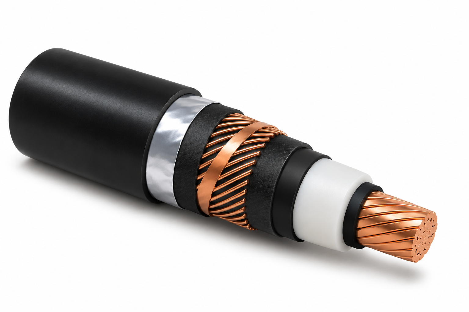
Construction
Illustrated variant: Sample B: copper conductor, copper-wire screen, aluminium-foil barrier, PE sheath
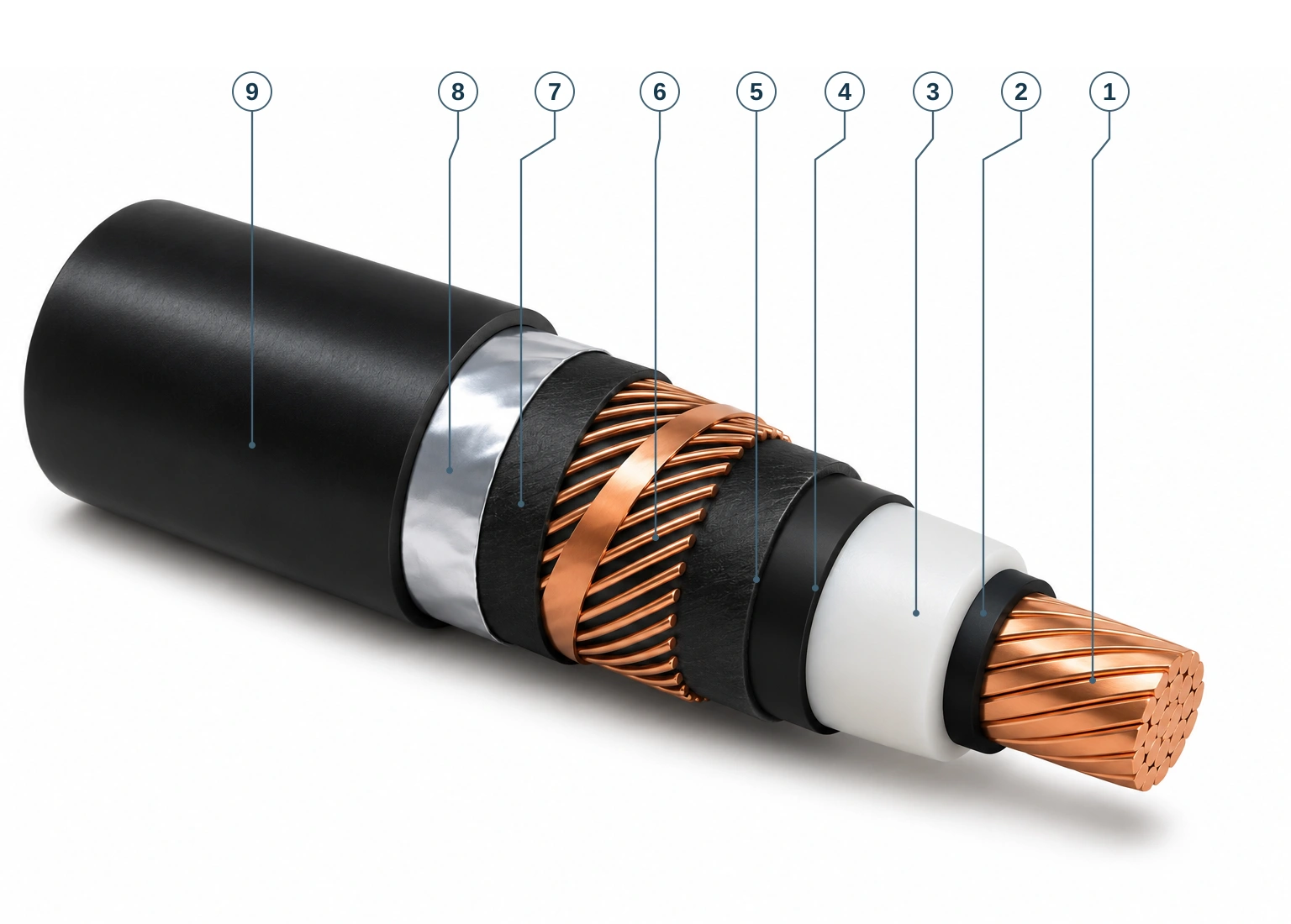
- Compacted stranded copper conductor
Copper strands are compacted together to form the current-carrying conductor.
- Semiconducting conductor screen
A semiconducting layer around the conductor forms the inner electrical screen.
- XLPE insulation
Cross-linked polyethylene forms the main electrical insulation around the conductor.
- Semiconducting insulation screen
A semiconducting layer around the XLPE insulation forms the outer insulation screen.
- Semiconducting water-blocking tape bedding
Semiconducting water-blocking tape forms the bedding beneath the metallic screen.
- Copper wire helix and counter-helix copper contact tape
Helically applied copper wires and counter-helix copper contact tape form the metallic screen.
- Water-blocking and binder separation tape
The tape forms a binding and separating layer between the metallic screen and the foil barrier.
- Aluminium foil laminate water barrier
The aluminium foil laminate forms a water barrier beneath the PE sheath; it is not wire armour.
- PE outer sheath
Polyethylene forms the external protective sheath around the selected Sample B construction.
Sample B illustration: supplier HV reference catalogue, page 2, with copper-wire screen, aluminium-foil laminate water barrier and PE outer sheath. This is not the lead-sheath construction used by the dimensional and weight reference tables on supplier HV reference catalogue, page 3.
Construction source: supplier HV reference catalogue, page 2.
Family reference
| Illustrated conductor | Copper |
|---|---|
| Illustrated configuration | stranded compacted copper, copper wire screen, aluminium foil water barrier |
| Construction layers | stranded compacted copper conductor; semiconducting conductor screen; XLPE insulation; semiconducting insulation screen; semiconducting water-blocking tape bedding; copper wire helix plus copper contact tape counter-helix; semiconducting water-blocking/binder separation tape; aluminium foil laminate radial water barrier; PE outer sheath |
| Selection requirement | Confirm size, rated voltage, installation conditions and applicable standards before ordering |
36/66 kV sample construction data
Single-core XLPE-insulated high-voltage cable. The supplier reference lists aluminium and copper conductor configurations, with nominal conductor areas from 240 to 2000 mm².
- Rated voltage U0/U
- 36/66 kV
- Um
- 72.5 kV
- Up
- 350 kV
| Nominal conductor area (mm²) | Outer diameter — aluminium conductor (mm) | Outer diameter — copper conductor (mm) | Net weight with Pb sheath — aluminium conductor (kg/m) | Net weight with Pb sheath — copper conductor (kg/m) | Minimum bending radius during laying (m) |
|---|---|---|---|---|---|
| 240 | 63 | 64 | 9.9 | 11.5 | 1.6 |
| 400 | 66 | 71 | 10.5 | 13.2 | 1.8 |
| 630 | 72 | 76 | 11.5 | 15.9 | 1.9 |
| 800 | 73 | 78 | 11.9 | 17.3 | 2.0 |
| 1000 | 77 | 88 | 12.7 | 21.1 | 2.2 |
| 1200 | 77 | 91 | 13.0 | 22.1 | 2.3 |
| 1600 | 96 | 96 | 15.5 | 26.4 | 2.4 |
| 2000 | 103 | 103 | 16.5 | 29.6 | 2.6 |
| Nominal conductor area (mm²) | Maximum DC resistance at 20°C — aluminium conductor (Ω/km) | Maximum DC resistance at 20°C — copper conductor (Ω/km) |
|---|---|---|
| 240 | 0.1250 | 0.0754 |
| 400 | 0.0778 | 0.0470 |
| 630 | 0.0469 | 0.0283 |
| 800 | 0.0367 | 0.0221 |
| 1000 | 0.0291 | 0.0176 |
| 1200 | 0.0247 | 0.0151 |
| 1600 | 0.0186 | 0.0113 |
| 2000 | 0.0149 | 0.0090 |
Supplier catalogue sample-construction reference, not a statement of current stock or a guaranteed project design. Dimensions and weights apply to the referenced sample constructions; the weight figures explicitly use a Pb (lead) sheath basis. Final construction, dimensions, ratings and approved drawings require project-specific confirmation with the official quotation.
Current-carrying capacity depends on the final installation and thermal conditions. Project-specific ratings and applicable standards must be confirmed during technical review.
Catalogue standard reference
IEC 60183 is cited in the supplier catalogue’s explanation of the relationship between U0/U and Um in three-phase systems. This is reference context, not a declaration that the numerical sample above is certified or compliant with a particular product standard. The applicable standard, edition and test scope must be agreed for the project.
Illustration and numerical sample may represent different construction variants. Catalogue weights, dimensions and data are approximate references, not guaranteed production values.
Project-specific confirmation
Confirm the required conductor material, core arrangement, voltage designation, installation conditions, size and applicable standards with your enquiry. Reference tables on this page give data for the stated construction; confirm the selected current datasheet before ordering.
Illustrations are not engineering drawings or factory photographs. Final specifications and approved drawings will be confirmed with our official quotation. No certification or current manufacturer availability is implied by this family overview.