Construction & selection
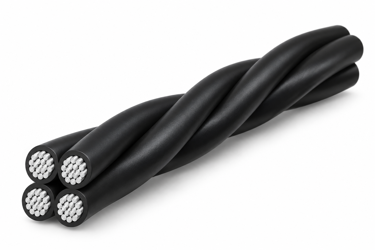
Aerial bundled cable configurations with individually insulated aluminium conductors. The illustration shows four insulated conductors twisted together, with no separate bare messenger or common sheath. Other messenger and street-lighting arrangements are separate selections; the applicable voltage rating must be confirmed.
For technical data and a quotation, use Contact in the main navigation and include this cable family in your enquiry.
Construction
Illustrated variant: Four individually insulated aluminium distribution conductors
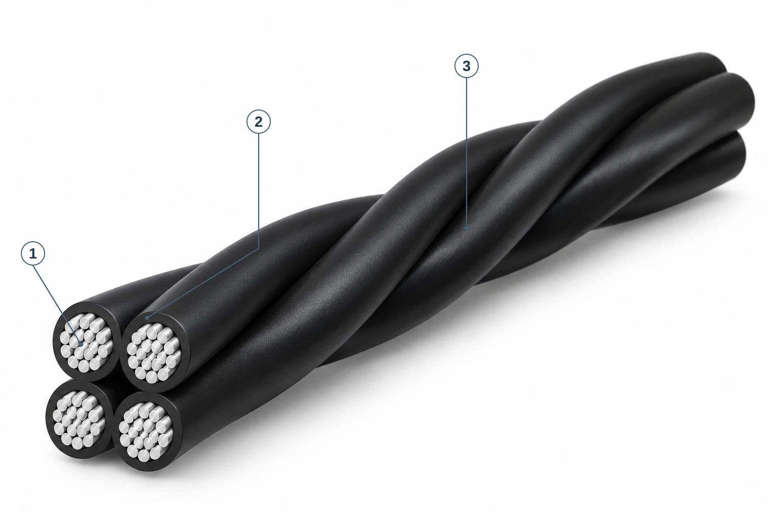
- Aluminium conductors
The aluminium conductors form the current-carrying elements of the insulated cores.
- Individual XLPE insulation
Each aluminium conductor has its own XLPE insulation within the four-conductor bundle.
- Four-conductor twisted bundle
Four individually insulated aluminium conductors are twisted together; no separate messenger or common sheath is shown.
The image shows four individually XLPE-insulated aluminium conductors. Separate messenger and lighting add-on arrangements, and the PE insulation alternative, are not illustrated.
Construction source: supplier overhead conductor reference catalogue, page 43.
Family reference
| Illustrated conductor | Aluminium |
|---|---|
| Illustrated configuration | Four equal insulated distribution wires; no separate messenger or lighting wire |
| Construction layers | four stranded aluminium conductors; individual XLPE covering selected from p42 option; twisted bundle without common sheath |
| Selection requirement | Confirm size, rated voltage, installation conditions and applicable standards before ordering |
Engineering data
Manufacturer catalogue reference: PDF page 43 (printed page 39).
Unresolved source conflict:0.6/1 kV versus600 V application limit.
Source p.42 cites NF C 33-209, BS 7870, NF C 31-122 and NF C 32-013; catalogue references only.
| Cable configuration (source notation) (mm²) | Distribution conductor configuration (mm²) | Number of distribution wires (No.) | Distribution diameter (source heading: diameter of wires) (mm) | Distribution resistance at 20°C (Ω/km) | Distribution current at 30°C (A) | Street-lighting configuration (mm²) | Street-lighting current (A) | Messenger diameter (mm) | Minimum messenger tensile strength (kN) | Messenger resistance at 20°C (Ω/km) | Approx. maximum bundle diameter (mm) | Approx. net weight (kg/km) |
|---|---|---|---|---|---|---|---|---|---|---|---|---|
| 2*16 | 2*16 | 7 | 4.6 | 1.91 | 93 | Not specified | Not specified | Not specified | Not specified | Not specified | 15 | 132 |
| 2*25 | 2*25 | 7 | 5.9 | 1.2 | 122 | Not specified | Not specified | Not specified | Not specified | Not specified | 18.5 | 200 |
| 2*35 | 2*35 | 7 | 6.9 | 0.868 | 129 | Not specified | Not specified | Not specified | Not specified | Not specified | 22 | 280 |
| 2*50 | 2*50 | 7 | 8.1 | 0.641 | 158 | Not specified | Not specified | Not specified | Not specified | Not specified | 24 | 370 |
| 4*16 | Not specified | 7 | 4.6 | 1.91 | 83 | Not specified | Not specified | Not specified | Not specified | Not specified | 18 | 265 |
| 4*25 | 4*25 | 7 | 5.9 | 1.2 | 111 | Not specified | Not specified | Not specified | Not specified | Not specified | 22 | 400 |
| 4*35 | 4*35 | 7 | 6.9 | 0.868 | 131 | Not specified | Not specified | Not specified | Not specified | Not specified | 26 | 550 |
| 3*25+54.6 | 3*25 | 7 | 5.9 | 1.2 | 112 | Not specified | Not specified | 9.6 | 16 | 0.63 | 30 | 470 |
| 3*25+1*16+54.6 | 3*25 | 7 | 5.9 | 1.2 | 112 | 1*16 | 60 | 9.6 | 16 | 0.63 | 30 | 570 |
| 3*25+2*16+54.6 | 3*25 | 7 | 5.9 | 1.2 | 112 | 2*16 | Not specified | 9.6 | 16 | 0.63 | 30 | 640 |
| 3*35+54.6 | 3*35 | 7 | 6.9 | 0.868 | 138 | Not specified | Not specified | 9.6 | 16 | 0.63 | 33 | 580 |
| 3*35+1*16+54.6 | 3*35 | 7 | 6.9 | 0.868 | 138 | 1*16 | 60 | 9.6 | 16 | 0.63 | 33 | 690 |
| 3*35+2*16+54.6 | 3*35 | 7 | 6.9 | 0.868 | 138 | 2*16 | Not specified | 9.6 | 16 | 0.63 | 33 | 750 |
| 3*50+54.6 | 3*50 | 7 | 8.1 | 0.641 | 168 | Not specified | Not specified | 9.6 | 16 | 0.63 | 36 | 720 |
| 3*50+1*16+54.6 | 3*50 | 7 | 8.1 | 0.641 | 168 | 1*16 | 60 | 9.6 | 16 | 0.63 | 36 | 820 |
| 3*50+2*16+54.6 | 3*50 | 7 | 8.1 | 0.641 | 168 | 2*16 | Not specified | 9.6 | 16 | 0.63 | 36 | 890 |
| 3*70+54.6 | 3*70 | 12 | 9.7 | 0.443 | 213 | Not specified | Not specified | 9.6 | 16 | 0.63 | 38 | 930 |
| 3*70+1*16+54.6 | 3*70 | 12 | 9.7 | 0.443 | 213 | 1*16 | 60 | 9.6 | 16 | 0.63 | 38 | 1030 |
| 3*70+2*16+54.6 | 3*70 | 12 | 9.7 | 0.443 | 213 | 2*16 | Not specified | 9.6 | 16 | 0.63 | 38 | 1100 |
| 3*70+1*25+54.6 | 3*70 | 12 | 9.7 | 0.443 | 213 | 1*25 | Not specified | 9.6 | 16 | 0.63 | 40 | 1070 |
| 3*70+2*25+54.6 | 3*70 | 12 | 9.7 | 0.443 | 213 | 2*25 | Not specified | 9.6 | 16 | 0.63 | 40 | 1170 |
| 3*70+70 | 3*70 | 12 | 9.7 | 0.443 | 213 | Not specified | Not specified | 10.2 | 20.6 | 0.5 | 41 | 970 |
| 3*70+1*16+70 | 3*70 | 12 | 9.7 | 0.443 | 213 | 1*16 | 60 | 10.2 | 20.6 | 0.5 | 41 | 1080 |
| 3*70+2*16+70 | 3*70 | 12 | 9.7 | 0.443 | 213 | 2*16 | Not specified | 10.2 | 20.6 | 0.5 | 41 | 1150 |
| 3*95+70 | 3*95 | 19 | 11.5 | Not specified | 258 | Not specified | Not specified | 10.2 | 20.6 | 0.5 | 44 | 1200 |
| 3*95+1*16+70 | 3*95 | 19 | 11.5 | 0.32 | 258 | 1*16 | 60 | 10.2 | 20.6 | 0.5 | 44 | 1300 |
| 3*95+2*16+70 | 3*95 | 19 | 11.5 | 0.32 | 258 | 2*16 | Not specified | 10.2 | 20.6 | 0.5 | 44 | 1380 |
| 3*120+70 | 3*120 | 19 | 12.8 | 0.253 | 300 | Not specified | Not specified | 10.2 | 20.6 | 0.5 | 46 | 1430 |
- Source p.42 describes 0.6/1 kV and 600/1000 V marking but also says service at600 V or lower. Rated voltage must be confirmed on the corrected product datasheet before selection.
- Current column is headed30°C; no unsupported installation assumptions are added.
- A dash means not provided in the source; blank source street-lighting current cells remain unspecified.
- Source diameter-of-wires heading appears inconsistent with conductor-sized values; values retained with original-heading disclosure, not recast as individual strand diameters.
- The distribution resistance for configuration 3*95+70 conflicts with related source rows; the affected cell is withheld pending manufacturer confirmation.
- Values are transcribed from the supplied manufacturer catalogue, not independently certified test results. Final construction, applicable standard edition and project suitability require technical review.
Project-specific confirmation
Confirm the required conductor material, core arrangement, voltage designation, installation conditions, size and applicable standards with your enquiry. Reference tables on this page give data for the stated construction; confirm the selected current datasheet before ordering.
Illustrations are not engineering drawings or factory photographs. Final specifications and approved drawings will be confirmed with our official quotation. No certification or current manufacturer availability is implied by this family overview.